| PARAMETER |
SPECIFICATION |
| Input Voltage |
415V ±10% A C, 50Hz, Three Phase |
| Ambient temperature |
40˚C |
| Method of cooling |
Air-cooled |
| Type of Transformer |
Epoxy cast dry type rectifier transformer |
| Duty |
Continuous operation |
| Installation |
Indoor |
| Protections |
Input HRC fuses
Single phasing preventer
Harmonic filter at the mains input
Thermal overload relays
Linear reactor for limiting short circuit current |
| Digital Monitoring |
Acceleration voltage – 0 to -15kV DC average
Beam current – 0 to 1A DC mean |
| Controls & Signals on Control Panel |
Push buttons for ON/ OFF
10 turn potentiometer for voltage, current control
LED indications for ON/ OFF, fault status |
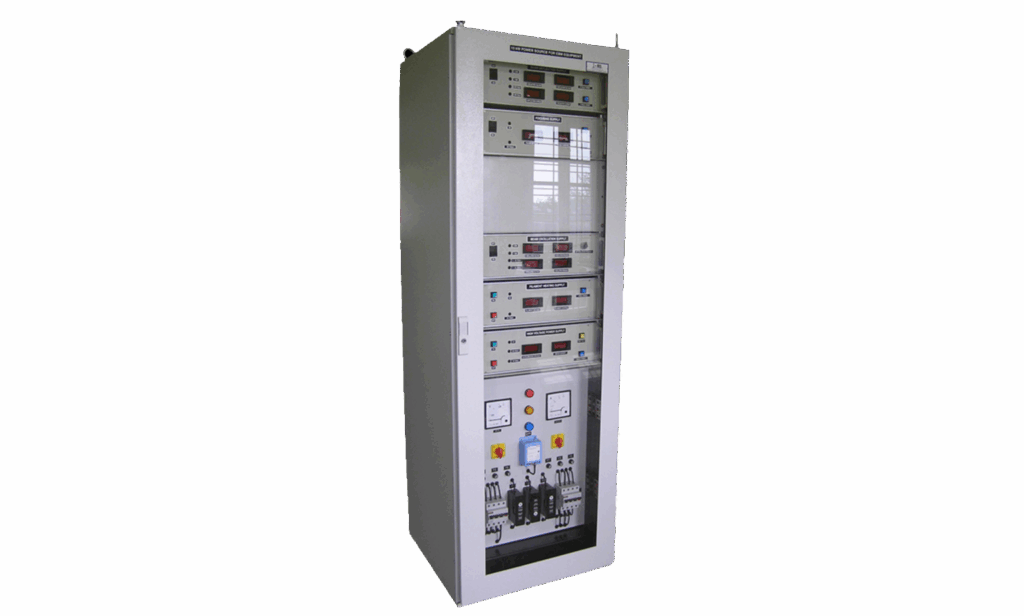
| Construction |
The unit is to be divided into three parts viz.,
The transformer cubicle, control cubicle and control console |
| ACCELERATION VOLTAGE SUPPLY |
| Output Voltage Range |
-0.5kV DC to -15kV DC average |
| Output Current Range |
0 to 1A mean |
| Line Regulation |
Upto 4% for 10% variation in input voltage |
| Load Regulation |
Upto 4% for 0 to 100% load variation |
| Stability |
< 10% |
| Ripple at frequencies ≤ 1 kHz |
Upto 4% rms of set value – within working range |
| Resolution |
0.5kV for voltage and 10mA for current |
| Protections* |
Against over load, over current, over voltage, over watts and short -circuit. During short circuit power supply trips |
| FILAMENT HEATING SUPPLY (EHT INSULATED) |
| Output Voltage Range |
0 to 7V AC rms |
| Output Current Range |
0 to 40A |
| Insulation Level |
This supply will be floating at -15kV DC |
| Protections |
The power supply will incorporate trip circuit for over current fault. |
| Topology |
Thyristorised primary controller followed by single phase step down transformer, independent close loop control |
| FOCUSING SUPPLY |
| Output Voltage Range |
Upto 70V DC |
| Output Current Range |
0 to 1A |
| Ripple |
≤ 0.1% |
| Resolution |
1mA |
| BEAM OSCILLATION SUPPLIES (X & Y) 2 SETS |
| Output Voltage Range |
0 to 10V A C sinusoidal |
| Output Current Range |
0 to 1A (max) continuously variable by multi-turn potentiometer. |
| Frequency |
Variable from 3Hz to 50Hz, sinusoidal and saw tooth with selector switch |
| Phase Shift* |
Adjustable phase shift of 0 – 180˚ between the two sets of output |
| Line Regulation |
Upto 0.1% for 10% variation in input voltage |
| Load Regulation |
Upto 0.1% |
| BEAM DEFLECTION SUPPLIES (X & Y) 2 SETS |
| Voltage |
0 to 5V DC |
| Current |
0 to 0.5A (max) continuously variable by multi turn potentiometer. |
| Polarity |
Positive / negative (selectable through switch) |
| Line Regulation |
Upto 0.1% for all changes in line voltage of ±10% |
| Load Regulation |
Upto 0.1% |
| Ripple |
< 1mV rms |