| PARAMETER |
SPECIFICATION |
| Input Voltage |
115V or 230V± 10% AC, 50Hz, single phase |
| Output Voltage* |
0 to 10/20/30/40/50/60kV DC |
| Output Current |
0 to 400µA / 1mA |
| Polarity* |
Positive / Negative |
| Line Regulation |
<0.05% for±10% variation in input voltage |
| Load Regulation |
<0.05% for 10 to 100%load variation |
| Stability |
<0.01%hour after 1 hour warm up |
| Regulation Mode* |
Constant voltage |
| Voltage control (From zero to rated kV) |
By external 10-turn potentiometer with lockable counting dial |
| Protections |
Against overload, arc and short-circuit
During short circuit, power supply trips & to be manually reset to restart |
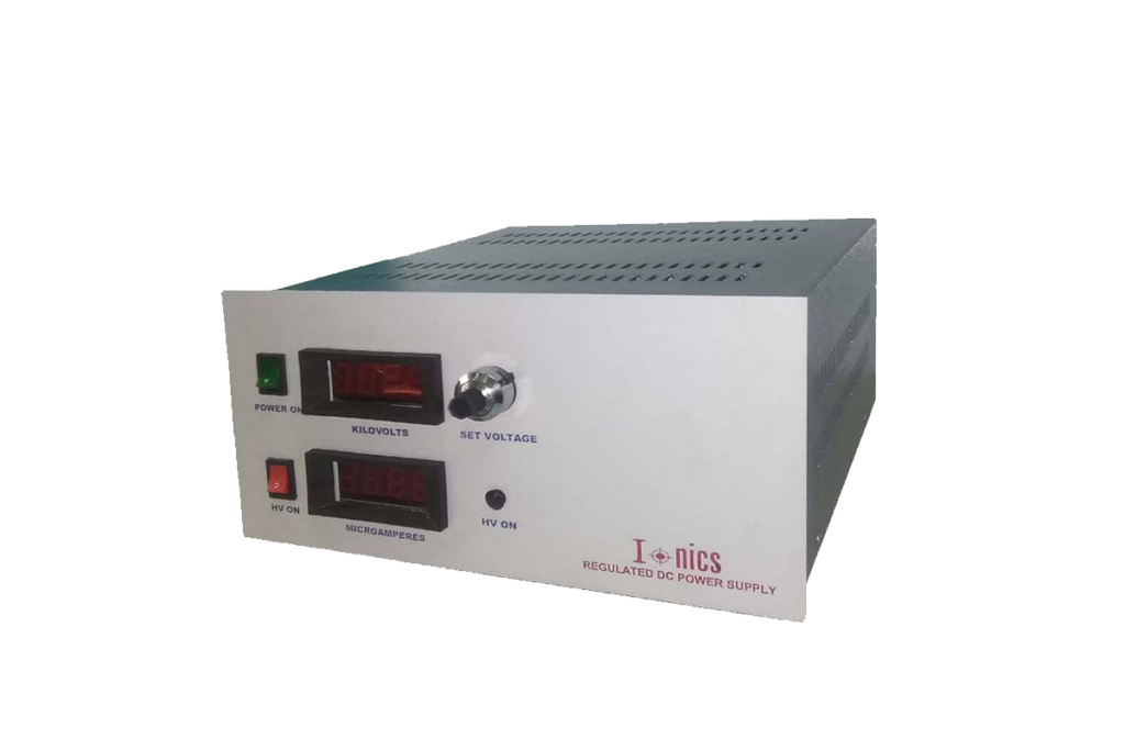
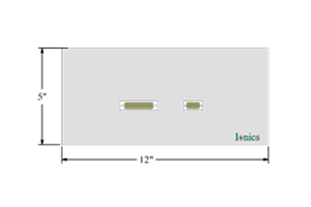
| Front Panel |
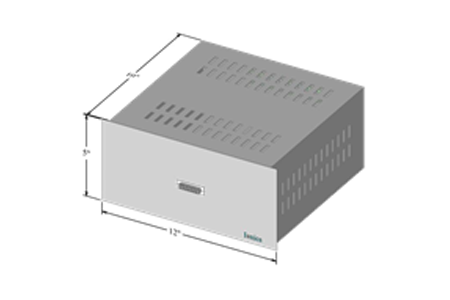
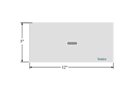
25pin D-connector for external operation
9pin D-connector for remote control |
Series I |
| 25pin D-connector for external operation |
Series II |
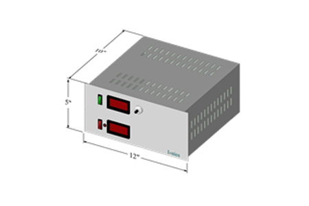
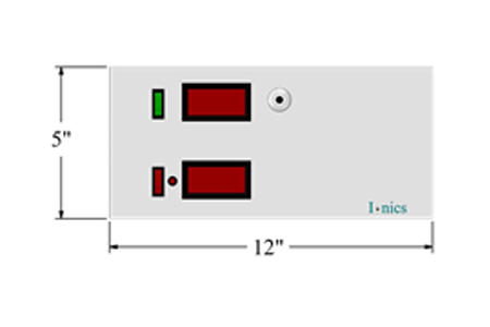
Power ON/OFF switch
HV ON/OFF switch with indication
3½ digit voltage and current meters
10-turn potentiometers for voltage and current control
Constant voltage – constant current mode indication
LED indications for faults |
Series III |
|
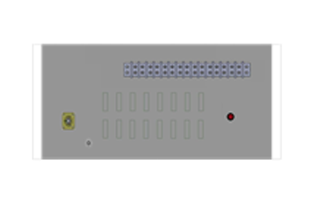
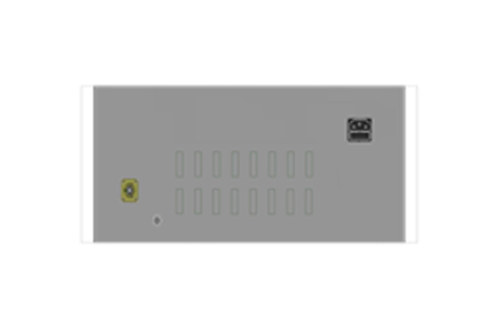
| Back Panel |
10pin terminal block
Fuse holder with fuse
RF connector for HV output
Stud for grounding the unit |
| Topology |
High frequency switch mode |
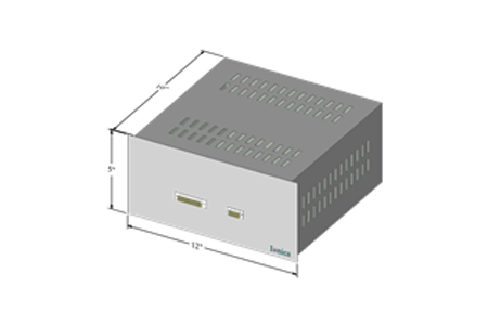
| Size |
10” x 10” x 5” (W x D x H) |
| Output cable |
1.5meters of HV DC cable |